This summer I decided to build a new antenna to upgrade from my previous one that didn’t preform very well. and there are many designs for antennas but this one had to fit these criteria:
It needed to be:
A: Multi band
B: Hard to see
C: Easy-ish to build
D: Cheap
The fan vertical looked like the perfect antenna fitting all the criteria.
Designing the Antenna
A fan vertical antenna is nothing more then multiple 1/4 wavelength antennas all connected to the same piece of coax. The calculations for that is pretty simple just: 234/Frequency in MHz (71.5/Frequency in MHz for meters), you should always add more then you think you need when making antennas yourself. For this antenna I added about 1.5 ft extra to each leg of the antenna.
Next part is the radials:
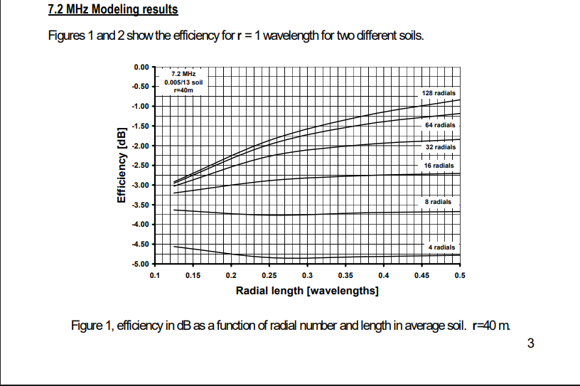
The image above shows how much power is getting absorbed by the ground at 7.2 mhz and shows as you add more radials and more length to each radial the more efficient the antenna is. For me I am using 8 radials at about 0.25 wavelengths long which means I lose over half of my power to the ground! Because dB is a logarithmic scale where every time you jump 3 dB its a doubling so for example if I’m putting 100 watts in the antenna and its attenuates (loses in this context) 3 dB to the ground I’m only getting 50 watts out assuming everything else is perfect about the antenna.
This graph assumes too that you have average soil conductivity. The map below shows soil conductivity in the USA.
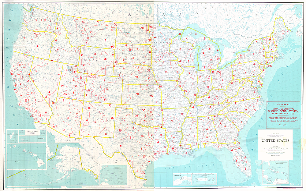
The number on the map to your location is how conductive your soil is, the more conductive you soil the more efficient your antenna will be. That being said its better to have many short radials rather then having a few long ones.
For the coax I used RG-8X because it has low attenuation, and is quite cheap.
Building the Antenna
My plan for building the antenna was as follows:
1: Put the 5 radiating elements on the tree
2: Connect them to a waterproof box that connects it all to the coax
3: A coax cable running through the yard into my room
The 5 radiating elements were cut pre-hand and then crimped with ring terminals. The box that connects the radiating elements to the coax is just a waterproof box drilled into the tree, with caulk to waterproof the wires entering and exiting the box.
Issues
While building the antenna was relatively easy, getting it to be tuned was a nightmare and I still cant figure it out. For some weird reason I was only getting 4 SWR dips instead of 5 and the dips themselves weren’t efficient managing at the lowest only 2 SWR (which is 11% of the total power getting reflected back.) No matter what I did I could not get it in tune. And having pretty much ran out of time due to the weather starting to get cold I could not work on the antenna for the rest of the year. A theory I’ve seen when talking to some people was that the radiating elements were causing them to react capacitively due to them being to close to each other.
Final Thoughts
In my opinion the fan vertical is a okay design. I think if I redesigned it, the antenna would’ve preformed much better. But anyways here are some pros and cons of this design.
Pros:
Multi-band
Easy-ish to build
Very hard to see if built right
Cons:
I could not get it tuned to a good SWR
You need radials and at HF frequencies its a pain digging them
Since the antenna is vertical you are more likely to get noise and cause interference
Leave a Reply